DIY Button Box - With Build instructions
Dec 5, 2017 2:23:02 GMT
XRF Formula1 and barpilot like this
Post by y22rydr on Dec 5, 2017 2:23:02 GMT
Here is my build for a custom button box. I have only used this with pCars 2 on XBOX One.
Parts cost: about $50
Time: <1 day (Probably could be done quicker, but this is my first build and a bit of an experiment)
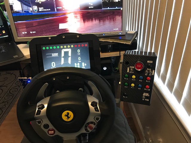
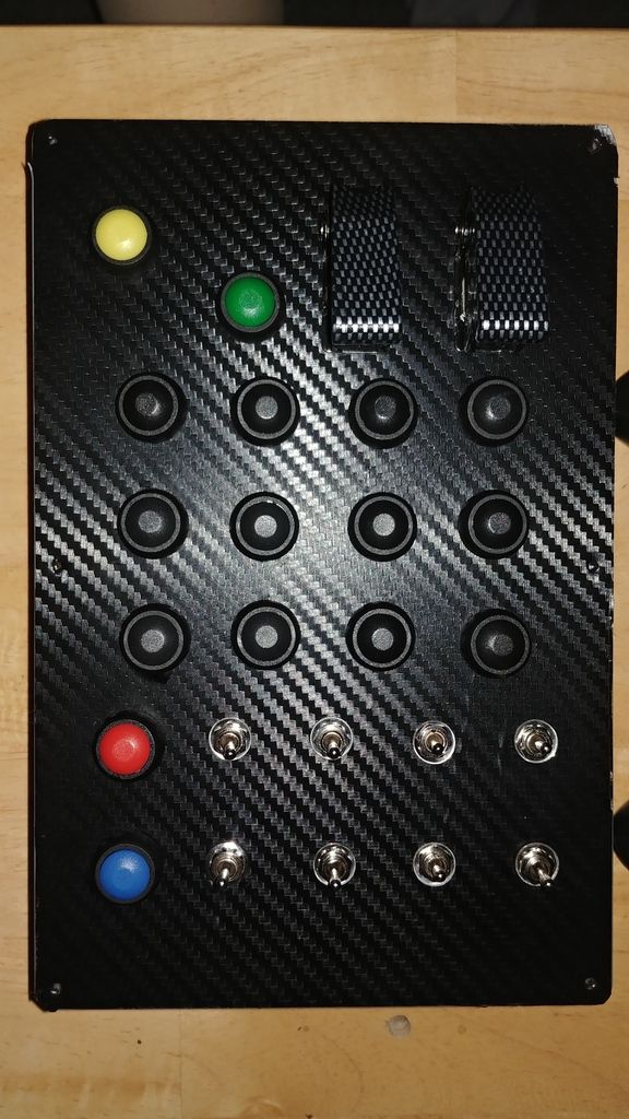
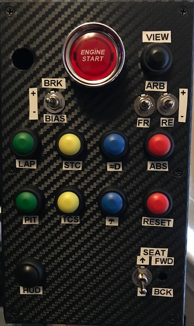
I am waiting for 2 switches to come in that is why you see 2 holes in the box.
Tools:
• Soldering pencil
• Wire cutter stripper
• Heat gun (or lighter for heat shrink tubing)
• Screwdriver
• Needle nose pliers
• Glue gun (with glue) or Epoxy
• Xacto knife
• Cutting Mat
• Carpenter square
• Machinist ruler
• Drill and bits
• Dremel
• Label maker
Parts:
• Old keyboard (probably can pick one up at a second-hand store if you do not have any laying around)
• Small gauge wire. (I used phone line and separated the wires. The wires are small and make it easier to solder to the surface of the board.)
• Heat shrink tubing (multiple sizes as appropriate)
• Various buttons and toggle switches (see below for ideas)
• Electronics project box (I used this one: Hammond 1591ESBK ABS Project Box Black (7.5” x 4.3”) ($7.51))
• Sheet Carbon fiber (AutoM New DIY Carbon Fiber Wrap Roll Sticker For Car Auto Vehicle Detailing 1.27Mx30CM ($5.99))
• Mounting hardware (will vary by rig)
Keyboard mapping:
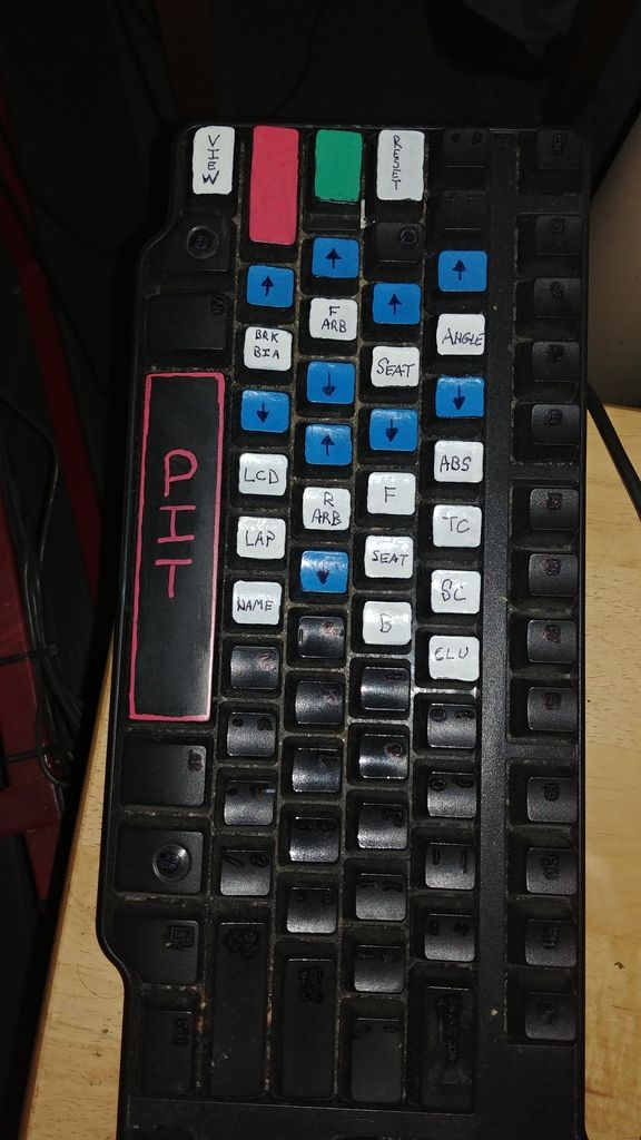
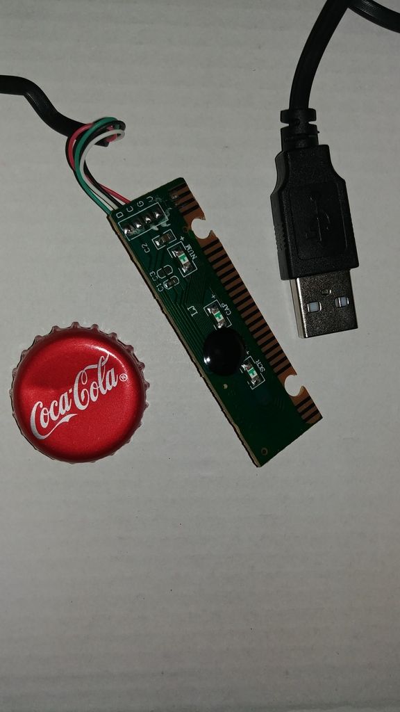
• Open the keyboard, and there should be a small board with two jacks that receive inputs from the keystrokes. Remove the plastic film-like keyboard inputs and remove the board from the keyboard housing. Keep the USB cable intact.
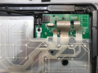
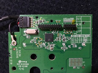
To identify the character generated by the pin combinations perform the following:
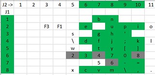
• Make a table with J1 pins on the left side. On the top list the J2 pins.
• Connect the USB cable to a computer.
• Open a program (I used excel and word) to record the keystrokes you will generate.
• Using a jumper wire connect J1 pins to J2 pins (J1-1 to J1-1) and see which character is generated
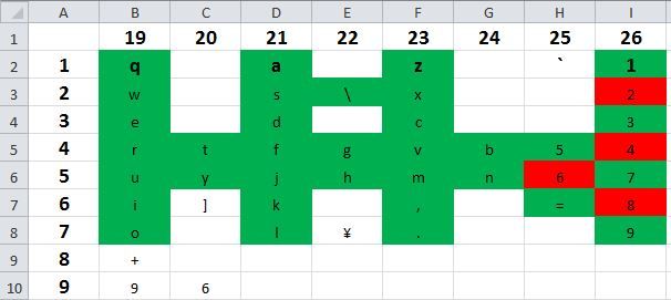
• Repeat until you have identified as many characters as you think you need (I suggest about 30, you do not want to use UP/DN/LEFT/RIGHT/2/4/6/8 as they are used for look left/right/up/down in the game already).
• I have included the results of my probing. I can’t guarantee yours will be the same (I used a Dell), but I suspect all keyboards are mapped the same.
Design Phase:
• Identify how many buttons you want/need for your button box. I decided on 24 buttons (after looking at the configuration tabs in Project Cars 2), and I wired the board for 28 in the event I wanted future expansion. Based on my desire I decided on the following (I have included the exact parts which I purchased through Amazon as well as my button mapping):
• Ignition – Toggle Switch with red cover // (SODIAL(R) DC 12V On Off Racing Car Illuminated Toggle Switch + Red Cover ($3.01) // Mapping used J1-2 (+) J2-6 (-)
• Start Engine – Push button // Jtron Dc 12v 50a Red Light Push Start Ignition Switch for Racing Sport OFF-(ON) momentary switch ($13.96) // Mapping from keyboard controller J1-4 (+) J2-6 (-)
Three positions momentary toggle for the following:
• Increase / Decrease Brake Bias // Mapping from keyboard controller J1-1 (Common) J2-7 (increase) J2-8 (decrease)
• Increase / Decrease Front ARBs // Mapping from keyboard controller J1-2 (Common) J2-8 (increase) J2-9 (decrease)
• Increase / Decrease Rear ARBs // Mapping from keyboard controller J1-3 (Common) J2-7 (increase) J2-8 (decrease)
• Seat Forward / Backward // Mapping from keyboard controller J1-4 (common) J2-9 (+) J2-10 (-)
• Seat Up / Down // Mapping from keyboard controller J1-5 (common) J2-9 (+) J2-10 (-)
• Part information: Uxcell a14112200ux0187 DPDT ON-OFF-ON Momentary Mini Toggle Switch AC 250V/2 Amp, 120V/5 Amp, 10 Piece ($12.81)
Momentary Pushbutton for the following:
• Headlights // Mapping from keyboard controller J1-6 (+) J2-6 (-)
• ABS // Mapping from keyboard controller J1-4 (+) J2-7 (-)
• Stability Control // Mapping from keyboard controller J1-5 (+) J2-7 (-)
• Traction Control // Mapping from keyboard controller J1-8 (+) J2-7 (-)
• Cycle Camera (View) // Mapping from keyboard controller J1-8 (+) J2-6 (-)
• Reset Car // Mapping from keyboard controller J1-4 (+) J2-8 (-)
• Show Lap Info // Mapping from keyboard controller J1-5 (+) J2-8 (-)
• Windscreen Wipers // Mapping from keyboard controller J1-6 (+) J2-8 (-)
• Cycle HUD // Mapping from keyboard controller J1-3 (+) J2-9 (-)
• Request Pit stop // Mapping from keyboard controller J1-8 (+) J2-8 (-)
• Part Information: 10 Pieces 12mm Waterproof Push Button Momentary On Off Switch ANKG-01 (5 Colors) ($8.99)
Modify the keyboard controller
Note: You may find a better way to attach the wires, but the following way worked for me
• Remove jacks (J1 and J2). I used a needle nose plier to rock the plastic part of the jacks up and off. This left behind some pins. I considered using those pins, but they were flimsy and came off the board easily. I endued up soldering lead wires directly to the board. You will have to do surface mounting, and I recommend that you tin the wires with enough solder so you can just heat the connection enough to stick it to the board.
NOTE: Ensure the wires are long enough so you can secure the controller inside the box and be able to open the lid (8 – 10 inches worked for me)
• I recommend that you using a helping hand with a magnifying glass because the connections are close together and small. Cover solder connections with epoxy or hot glue for extra durability.
• Also consider labeling each wire (i.e., J1-3, J2-5, etc.) for easier identification.
Determine your layout:
• I recommend using graphing paper in a 1:1 scale to draw it out.
Note: Keep in mind that the mounting hole is usually smaller than the button.
• Transfer your layout to the box. I used a pencil to draw it out.
• Cut holes to mount your buttons. Caution when you cut / drill your holes. Use lower speed to prevent the plastic from melting. Use the appropriate tool to smooth out the surface.
• Cut an opening in project box so you can feed the USB cable through.
• Determine how you are going to attach the box to your rig and drill appropriate holes (I have a Playseat Evolution with the center post). I used an “L” bracket (I used one which was 5mm thick because I wanted the bracket to be stiff and not move) and screwed it to the underside of the base which my wheel mounts to. I bought a longer bolt to compensate for the thickness of the bracket.
• Test fit some / all the buttons.
• Cover the plate with carbon fiber sheet (looks cool and covers any scratches you may have made). When cutting the carbon fiber leave an extra ¼” so you can wrap it around the edge.
• Lay the play face down on a cutting mat and trim out the carbon fiber from the holes.
• Flip it over and puncture the spots where the screws go through for final assembly (a small hole is sufficient.
Install buttons/switches and wire and assemble
• I soldered leads to the switches before I mounted them. If I did it again, I would mount the switches first and then make the connections because some of the switches share the same connection and I ended up with a lot of extra wire inside the project box.
• Wire the switches to the controller securing the connections by soldering and covering in heat shrink.
NOTE: Slide heat shrink onto the wire before soldering.
NOTE: Consider twisting the wires together and hooking it up to a computer to ensure all the buttons are working.
• Route cable through project box base.
• Secure keyboard controller to project box base using hot glue or epoxy
• Screw lid on
• Apply labels to buttons as desired.
• Plug into console and map buttons to verify everything works
• Mount to rig.
Enjoy!!
Parts cost: about $50
Time: <1 day (Probably could be done quicker, but this is my first build and a bit of an experiment)

I am waiting for 2 switches to come in that is why you see 2 holes in the box.

Tools:
• Soldering pencil
• Wire cutter stripper
• Heat gun (or lighter for heat shrink tubing)
• Screwdriver
• Needle nose pliers
• Glue gun (with glue) or Epoxy
• Xacto knife
• Cutting Mat
• Carpenter square
• Machinist ruler
• Drill and bits
• Dremel
• Label maker
Parts:
• Old keyboard (probably can pick one up at a second-hand store if you do not have any laying around)
• Small gauge wire. (I used phone line and separated the wires. The wires are small and make it easier to solder to the surface of the board.)
• Heat shrink tubing (multiple sizes as appropriate)
• Various buttons and toggle switches (see below for ideas)
• Electronics project box (I used this one: Hammond 1591ESBK ABS Project Box Black (7.5” x 4.3”) ($7.51))
• Sheet Carbon fiber (AutoM New DIY Carbon Fiber Wrap Roll Sticker For Car Auto Vehicle Detailing 1.27Mx30CM ($5.99))
• Mounting hardware (will vary by rig)
Keyboard mapping:
• Open the keyboard, and there should be a small board with two jacks that receive inputs from the keystrokes. Remove the plastic film-like keyboard inputs and remove the board from the keyboard housing. Keep the USB cable intact.


To identify the character generated by the pin combinations perform the following:
• Make a table with J1 pins on the left side. On the top list the J2 pins.
• Connect the USB cable to a computer.
• Open a program (I used excel and word) to record the keystrokes you will generate.
• Using a jumper wire connect J1 pins to J2 pins (J1-1 to J1-1) and see which character is generated
• Repeat until you have identified as many characters as you think you need (I suggest about 30, you do not want to use UP/DN/LEFT/RIGHT/2/4/6/8 as they are used for look left/right/up/down in the game already).
• I have included the results of my probing. I can’t guarantee yours will be the same (I used a Dell), but I suspect all keyboards are mapped the same.

Design Phase:
• Identify how many buttons you want/need for your button box. I decided on 24 buttons (after looking at the configuration tabs in Project Cars 2), and I wired the board for 28 in the event I wanted future expansion. Based on my desire I decided on the following (I have included the exact parts which I purchased through Amazon as well as my button mapping):
• Ignition – Toggle Switch with red cover // (SODIAL(R) DC 12V On Off Racing Car Illuminated Toggle Switch + Red Cover ($3.01) // Mapping used J1-2 (+) J2-6 (-)
• Start Engine – Push button // Jtron Dc 12v 50a Red Light Push Start Ignition Switch for Racing Sport OFF-(ON) momentary switch ($13.96) // Mapping from keyboard controller J1-4 (+) J2-6 (-)
Three positions momentary toggle for the following:
• Increase / Decrease Brake Bias // Mapping from keyboard controller J1-1 (Common) J2-7 (increase) J2-8 (decrease)
• Increase / Decrease Front ARBs // Mapping from keyboard controller J1-2 (Common) J2-8 (increase) J2-9 (decrease)
• Increase / Decrease Rear ARBs // Mapping from keyboard controller J1-3 (Common) J2-7 (increase) J2-8 (decrease)
• Seat Forward / Backward // Mapping from keyboard controller J1-4 (common) J2-9 (+) J2-10 (-)
• Seat Up / Down // Mapping from keyboard controller J1-5 (common) J2-9 (+) J2-10 (-)
• Part information: Uxcell a14112200ux0187 DPDT ON-OFF-ON Momentary Mini Toggle Switch AC 250V/2 Amp, 120V/5 Amp, 10 Piece ($12.81)
Momentary Pushbutton for the following:
• Headlights // Mapping from keyboard controller J1-6 (+) J2-6 (-)
• ABS // Mapping from keyboard controller J1-4 (+) J2-7 (-)
• Stability Control // Mapping from keyboard controller J1-5 (+) J2-7 (-)
• Traction Control // Mapping from keyboard controller J1-8 (+) J2-7 (-)
• Cycle Camera (View) // Mapping from keyboard controller J1-8 (+) J2-6 (-)
• Reset Car // Mapping from keyboard controller J1-4 (+) J2-8 (-)
• Show Lap Info // Mapping from keyboard controller J1-5 (+) J2-8 (-)
• Windscreen Wipers // Mapping from keyboard controller J1-6 (+) J2-8 (-)
• Cycle HUD // Mapping from keyboard controller J1-3 (+) J2-9 (-)
• Request Pit stop // Mapping from keyboard controller J1-8 (+) J2-8 (-)
• Part Information: 10 Pieces 12mm Waterproof Push Button Momentary On Off Switch ANKG-01 (5 Colors) ($8.99)
Modify the keyboard controller
Note: You may find a better way to attach the wires, but the following way worked for me
• Remove jacks (J1 and J2). I used a needle nose plier to rock the plastic part of the jacks up and off. This left behind some pins. I considered using those pins, but they were flimsy and came off the board easily. I endued up soldering lead wires directly to the board. You will have to do surface mounting, and I recommend that you tin the wires with enough solder so you can just heat the connection enough to stick it to the board.
NOTE: Ensure the wires are long enough so you can secure the controller inside the box and be able to open the lid (8 – 10 inches worked for me)
• I recommend that you using a helping hand with a magnifying glass because the connections are close together and small. Cover solder connections with epoxy or hot glue for extra durability.
• Also consider labeling each wire (i.e., J1-3, J2-5, etc.) for easier identification.
Determine your layout:
• I recommend using graphing paper in a 1:1 scale to draw it out.
Note: Keep in mind that the mounting hole is usually smaller than the button.
• Transfer your layout to the box. I used a pencil to draw it out.
• Cut holes to mount your buttons. Caution when you cut / drill your holes. Use lower speed to prevent the plastic from melting. Use the appropriate tool to smooth out the surface.
• Cut an opening in project box so you can feed the USB cable through.
• Determine how you are going to attach the box to your rig and drill appropriate holes (I have a Playseat Evolution with the center post). I used an “L” bracket (I used one which was 5mm thick because I wanted the bracket to be stiff and not move) and screwed it to the underside of the base which my wheel mounts to. I bought a longer bolt to compensate for the thickness of the bracket.
• Test fit some / all the buttons.
• Cover the plate with carbon fiber sheet (looks cool and covers any scratches you may have made). When cutting the carbon fiber leave an extra ¼” so you can wrap it around the edge.
• Lay the play face down on a cutting mat and trim out the carbon fiber from the holes.
• Flip it over and puncture the spots where the screws go through for final assembly (a small hole is sufficient.
Install buttons/switches and wire and assemble
• I soldered leads to the switches before I mounted them. If I did it again, I would mount the switches first and then make the connections because some of the switches share the same connection and I ended up with a lot of extra wire inside the project box.
• Wire the switches to the controller securing the connections by soldering and covering in heat shrink.
NOTE: Slide heat shrink onto the wire before soldering.
NOTE: Consider twisting the wires together and hooking it up to a computer to ensure all the buttons are working.
• Route cable through project box base.
• Secure keyboard controller to project box base using hot glue or epoxy
• Screw lid on
• Apply labels to buttons as desired.
• Plug into console and map buttons to verify everything works
• Mount to rig.
Enjoy!!


